

Technical Support
技术支持
Technical Support
技术支持LCD panel
1. LCD Features
Light weight and slim design
Low power consumption
Custom symbols and patterns easily included
High contrast in sunlight and wide viewing angle
Easy mounting and assembly
Wide range of applications
2. Comparison between TN, HTN, STN and FSTN technologies
| Item | Contrast ratio | Viewing angle | Cost |
| TN | 4 | 4 | 4 |
| HTN | 3 | 3 | 3 |
| STN | 2 | 2 | 2 |
| FSTN | 1 | 1 | 1 |
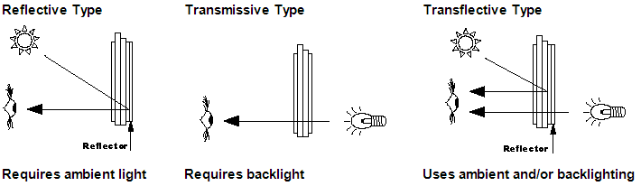
3. Differences between reflective, transflective and transmissive displays
Reflective LCD usually has a backing made of aluminum foil. This layer reflects the light that enters the front of the display. Reflective displays require ambient light for the light source since there is no backlight.
Transmissive LCD does not have a reflector or transflector laminated to the rear polarizer. A backlight must be used with this type of LCD configuration. The most common is a transmissive negative image. Transmissive LCD is usually clear. They have to be backlit to be able to see the infomation being displayed. Positive type transmissive will be dark dots or characters on a light background, negative will be dark background with light dots or characters.
Transflective LCD has an essential component (transflector, a polymer sheet) bonded to the rear polarizer, which enables light to pass through the back and reflect light from the front at the same time. Transflective = transmissive + reflective. Under bright illumination (e.g. when exposed to daylight) the display acts mainly as a reflective display with the contrast being constant with illuminance. Only in dim and dark ambient situations an auxiliary transmissive backlight should be provided. When an illuminance sensor is added for control of the backlight, such a transflective LCD can be read over a wide range of illuminance levels. This is why that technique is often found in automotive instrumentation. In portable electronic devices the transflective mode of operation helps to save battery charge, since in bright environments no backlighting is required.
Some displays which transmit light and have minor reflectivity are best readable in the dark, and fairly readable in bright sunlight, but under a particular angle only, and are least readable in bright daylight without direct sunlight. Under exposure to direct daylight, the image on non-reflective displays will completely wash out, and the display itself may be physically damaged.
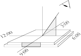
4. Viewing angle
Viewing Angle is the direction by which the display looks best (with best contrast). This is established during the manufacturing process and can not be changed by rotating the polarizer. Viewing direction is specified in terms of a clock position, such as 6:00 & 12:00. Please refer to the following drawing:
5. Conntor
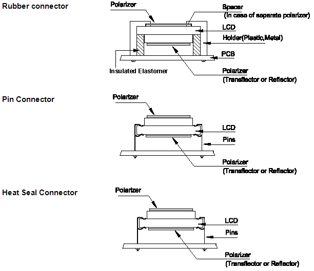
LCD module
1. Advantages and disadvantages of backlight versions
| Item | LED | EL | CCFL |
| Type | edge & array | thin flat panel | direct & edge lighting |
| Power requirement | DC 4.2V; high power consumption in array type | AC110~130V, 400Hz; needs DC/AC conberter; low power consumption | AC600~1000V, 30kHz; needs DC/AC converter; low power consumption |
| Brightness | 15~80cd/㎡ | 70~200cd/㎡ | 200~600cd/㎡ |
| Life | 50,000~100,000hr | 2,000~5,000hr | 10,000~20,000hr |
| Thickness | array: 5mm; edge: 1.30~4mm | 1.5mm (max) | direct: 15mm; edge: 3mm |
| Color | yellow/green, amber, red, orange, green, white | blue/green, white, yellow/green | white |
2. Clarification to the term “rainbow” effect
This refers to a red and green circle or rainbow on the LCD glass. The LCD panel under uneven pressure causes this problem from the bezel. This problem is very common in LCD modules and normally it will not affect the performance or the appearance of the display when operational.
3. What is temperature compensation and why is required?
A LCD operating voltage varies at different temperatures. The operating voltage must rise as temperature lowers or the contrast will degrade. Conversely, the operating temperature must fall as the temperature rises or the contrast will degrade. For this reason it is often a requirement, with graphics modules, to control the input voltage accordingly. The temperature compensation circuit is the circuit that controls the input voltage as the temperature changes. This temperature compensation circuit can be located on the LCD module or on the customer’s motherboard.
4. Troubleshooting an LED backlit module in which the display is turning dark
This problem is more than likely caused by the temperature rise from the LED backlight. In this case the LED backlight has consumed too much of the power. When the temperature rises, the VLCD requirements lower causing the input voltage to be too high. The result is a poor contrast and the display becoming too dark. The solution would be to lower the power consumption of the LED. This can be accomplished by raising the value of R8 or R9 to reduce the current to the LED backlight.